
*** This documentation provides an overview of my design and development process of a humanoid robot built from scratch. It is not intended to be a comprehensive “How-To” guide, but rather a high-level summary of the key steps and considerations involved. If you have any questions or need further details, please feel free to leave comments or reach out.
Introduction
As of 2024, the popularity of AI and robotics has skyrocketed. With my personal interest in these fields, building this project will provide a better understanding of the robotics and AI industries.
Building a robot from scratch involves a multitude of tasks and diverse fields. This might be the most ambitious project I have undertaken. The cost and the amount of engineering required make it a whole new realm of “Home DIY Projects.” The main reason for going through the entire process is to gain a deep understanding of kinematics, dynamics, and control theory, from hardware engineering to high-level AI applications. This project will help me get a better picture of what goes into building a humanoid robot from scratch.
Objective
- Design and build a complete dual-arm robot from scratch, enjoying the engineering process.
- Ensure it is low cost, durable, and reliable for robotics research purposes.
- Make it lightweight with a good power-to-load performance ratio.
- Ensure ROS2 support.
- Weigh less than 4.5 kg and capable of handling a 2.5 kg payload on the end effector.
Hardware Design Process
Choosing Motors
Selecting the right motors is crucial for the robot’s performance and accuracy. For this project, I chose Brushless Field-Oriented Control (FOC) motors due to their high efficiency, precise control, and excellent torque-to-weight ratio.
Factors Considered
- Power and Torque: These directly affect the robot’s ability to handle payloads and perform tasks accurately. Higher torque ensures the robot can lift and manipulate heavier objects, while adequate power ensures smooth and consistent operation.
- Efficiency: Brushless FOC motors are known for their high efficiency, which reduces energy consumption and heat generation, leading to longer operational times and better performance.
- Control Precision: FOC technology enables precise control of the motor’s position, speed, and torque, which is essential for tasks requiring high accuracy and repeatability. The choice of motor and type of reduction mechanism significantly impacts gear backlash and precision.
- Weight: The weight of the motors impacts the overall weight of the robot. Lighter motors help achieve a better power-to-load performance ratio, making the robot more agile and responsive.
Motor Selection Process
- Define Requirements: Establish the torque and power requirements based on the robot’s design and intended tasks, considering payload capacity and the range of motion needed for each joint.
- Evaluate Motor Options: Compare different brushless FOC motors based on their specifications, including torque, power, efficiency, and weight.
Script for Selecting the Best Motor for Each Joint
Download Script
To streamline the motor selection process, I developed a script that evaluates various motor options based on predefined criteria. This script takes into account factors such as estimated joint weight, motor weight, and link size to determine if the motor torque is sufficient for the build.
By inputting these parameters, the script quickly identifies the most suitable motor for each joint, ensuring optimal performance and efficiency. This approach simplifies the decision-making process and helps in achieving a balanced design.

Designing Robot Joint Links
Designing the robot joint links involves several key steps to ensure optimal performance and durability. The process begins with defining the requirements for each joint, including the range of motion, load capacity, and material constraints. Using CAD software, I create detailed models of each joint link, focusing on minimizing weight while maintaining structural integrity.
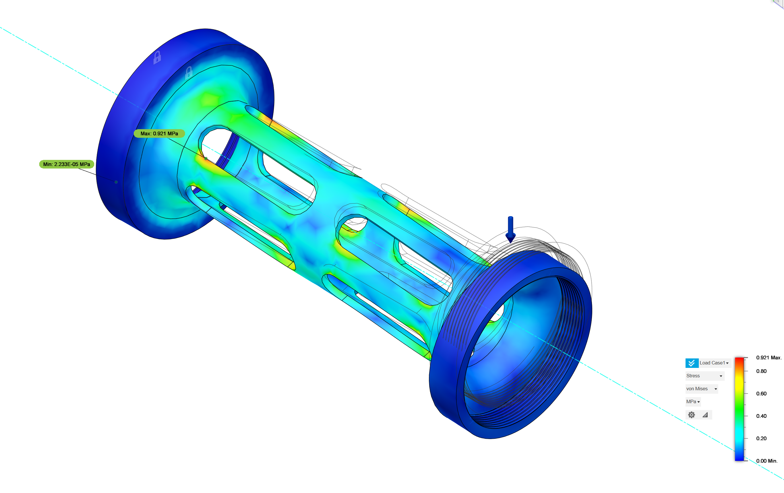
Using FEA Tool for Optimization
Finite Element Analysis (FEA) optimizes the weight and mechanical strength of each part by simulating various load conditions and stress distributions. This process involves iterating through design configurations to reduce material without compromising strength.
CAD Designs
In this section, I will walk you through the CAD design process of the robot arm.
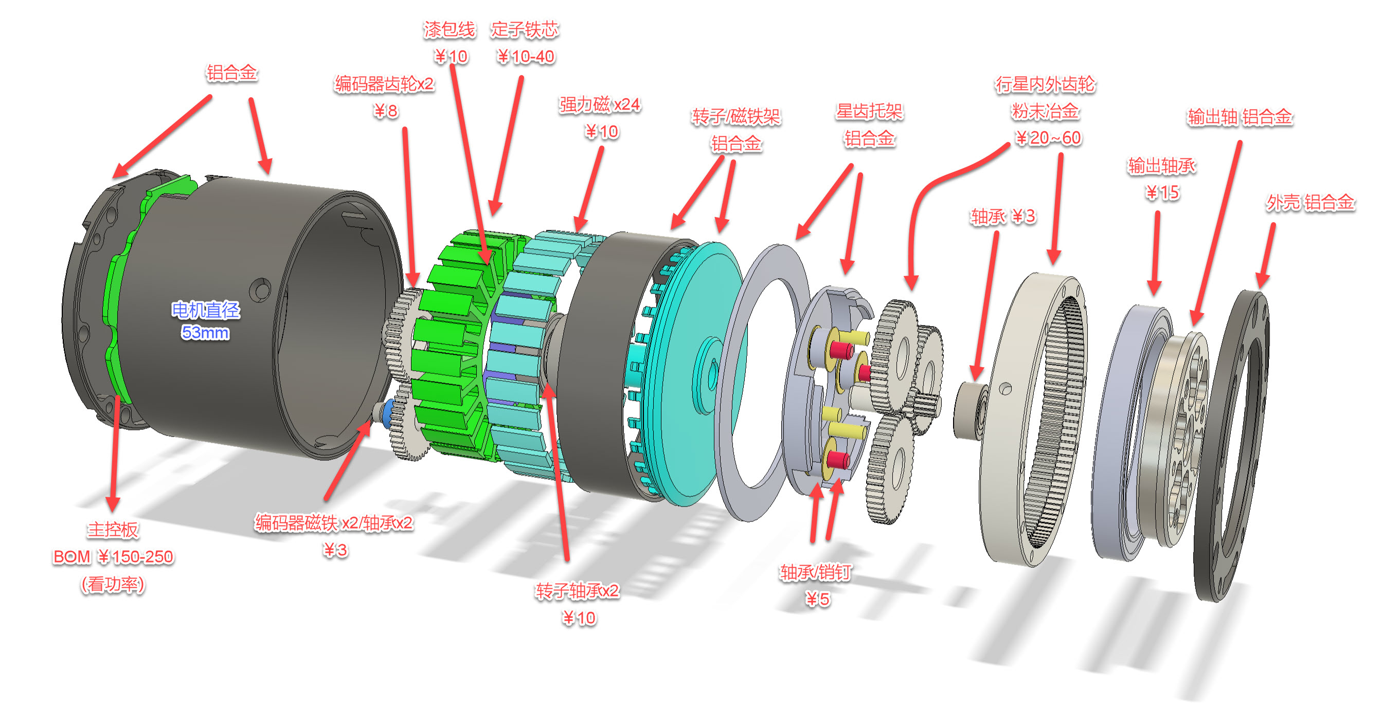
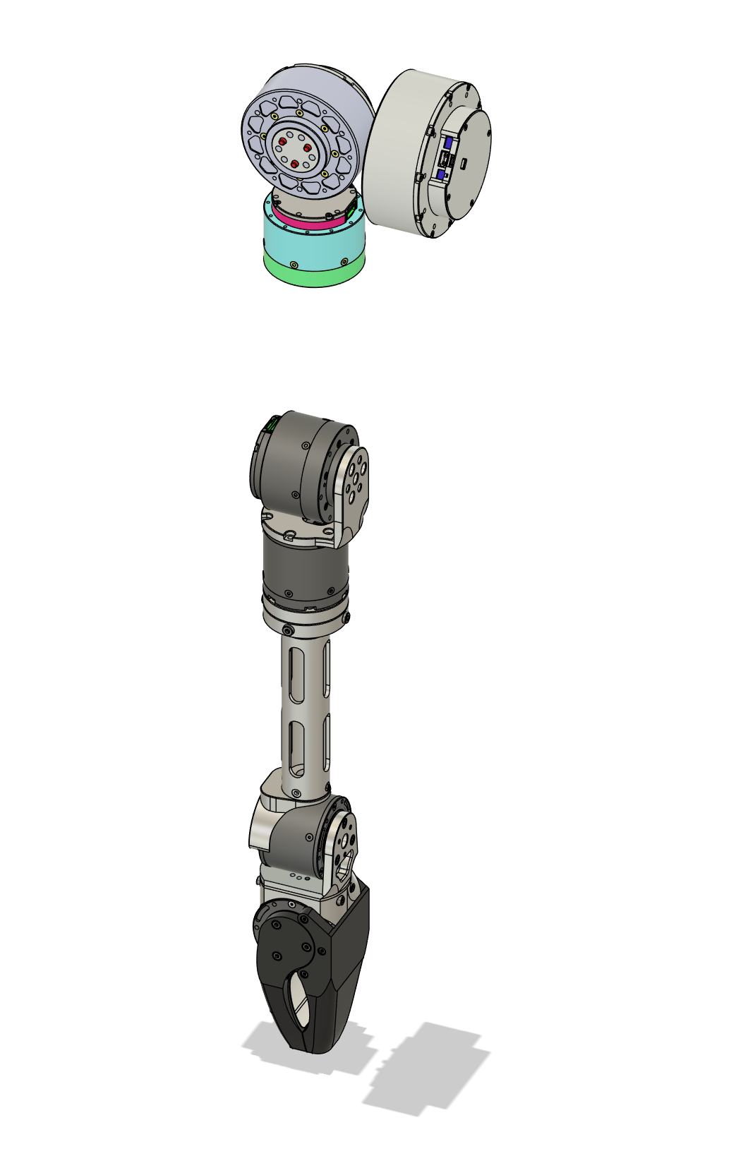
Motor Design
Motor I’m using:
- High Torque FOC Brushless Motors
- With 1:36 two-stage reduction gear
- Dual Encoder for precision and Absolute Zeroing Process
- CAN Protocol
- Torque ranges from
2.2Nmto55NmMotor Design Breakdown:
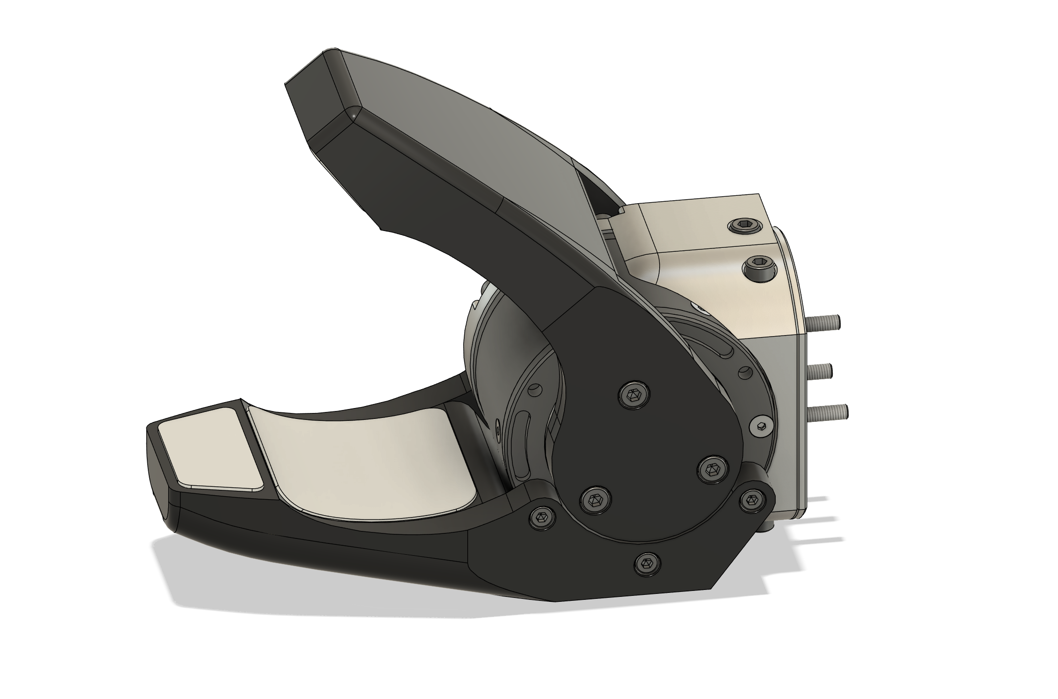
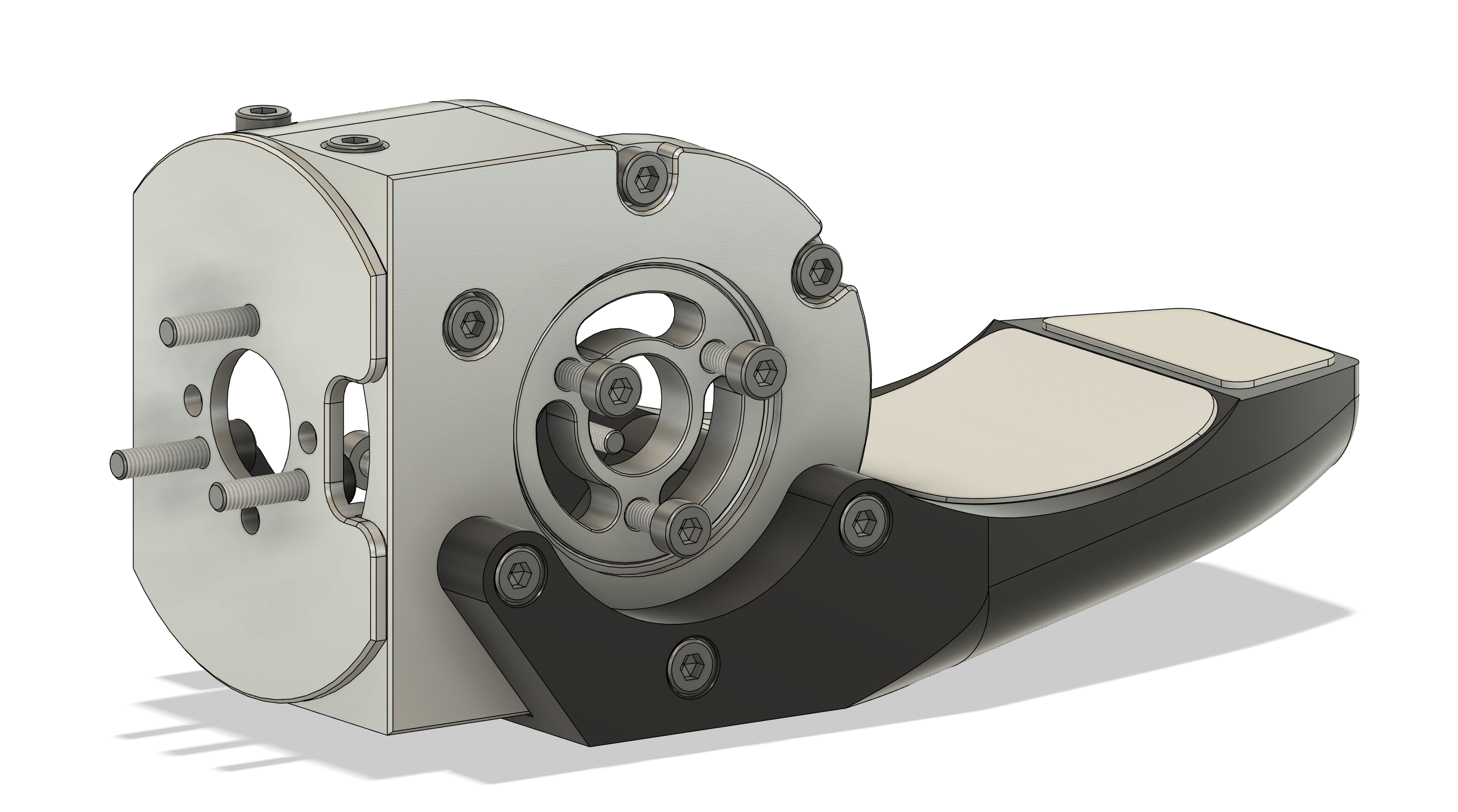
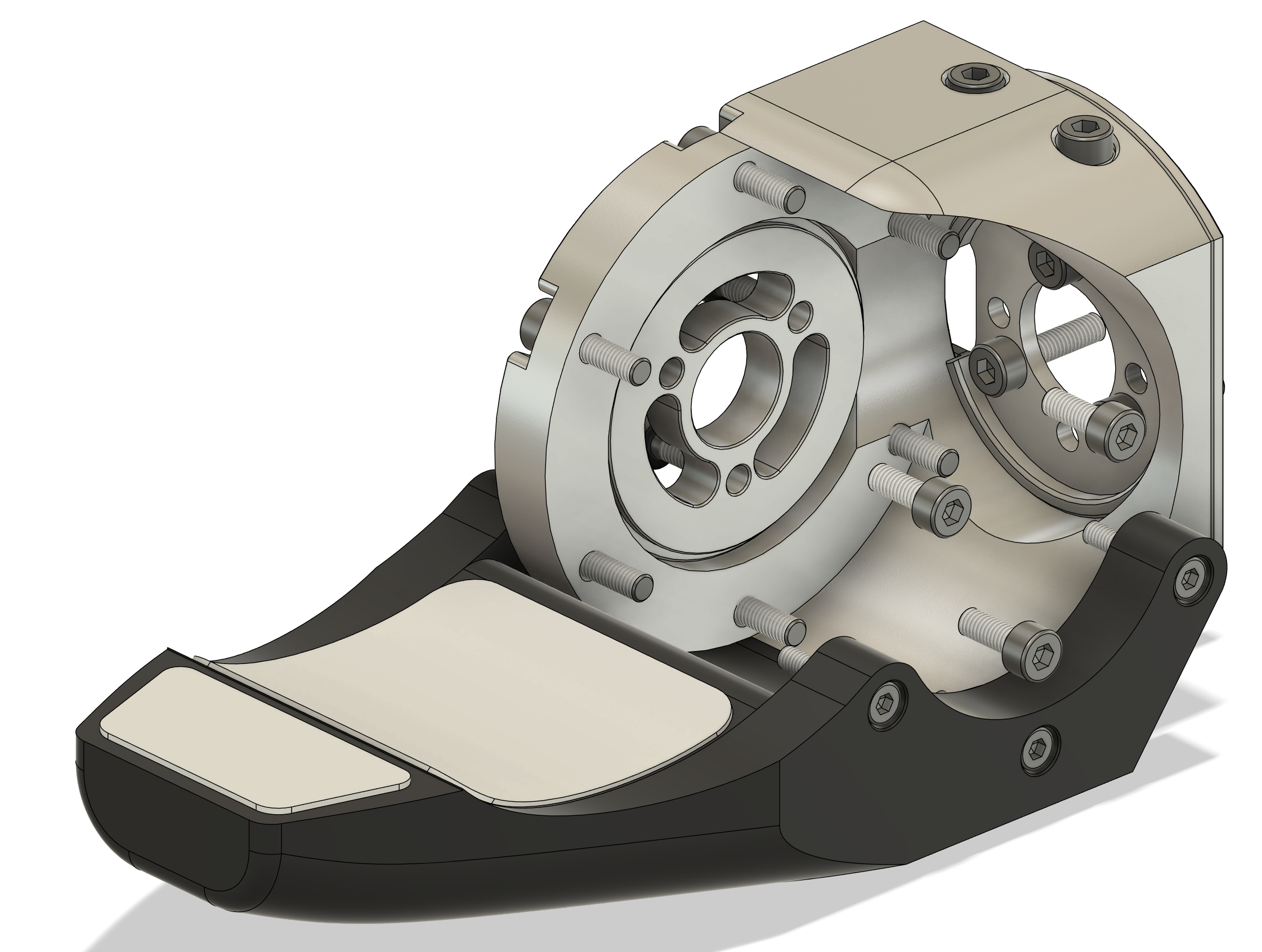
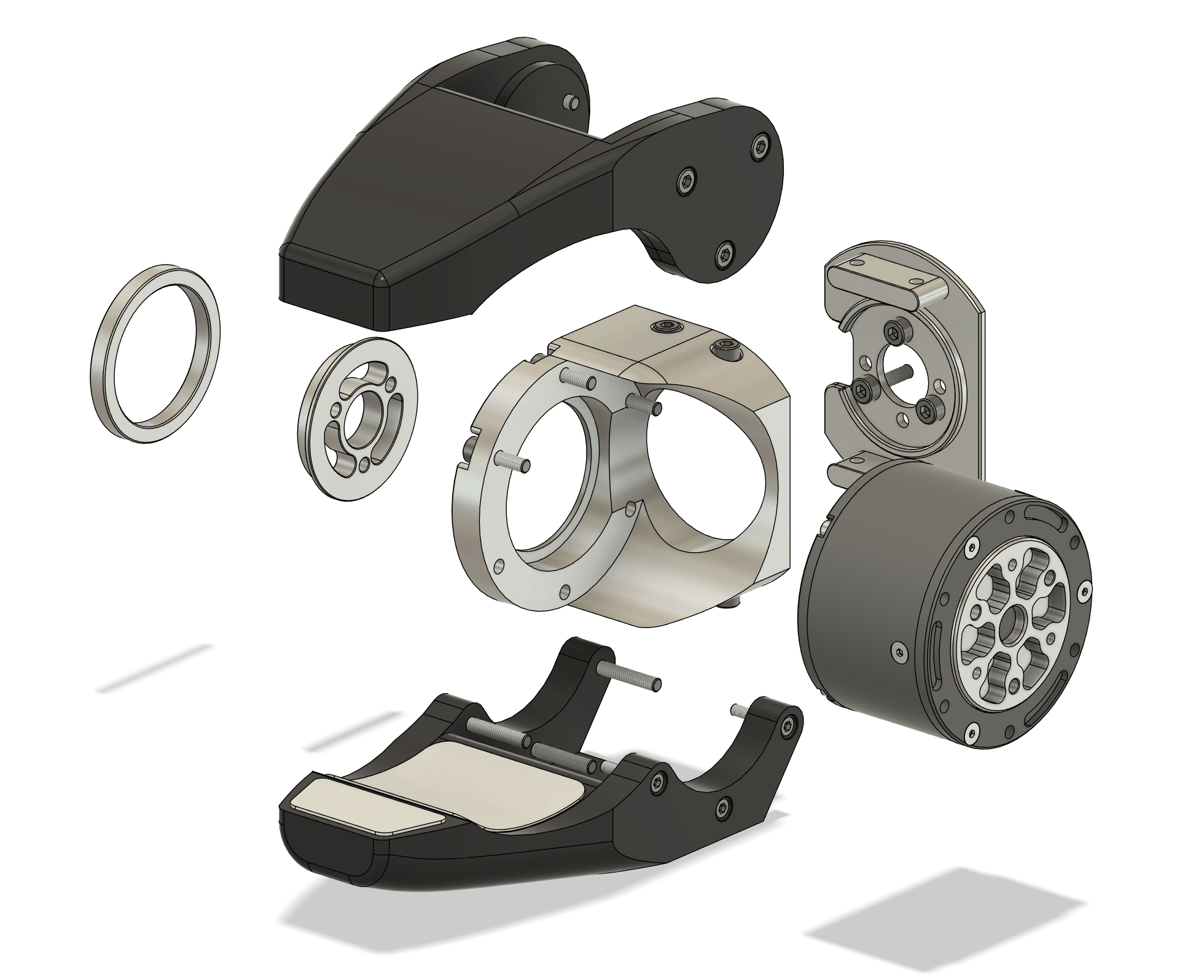
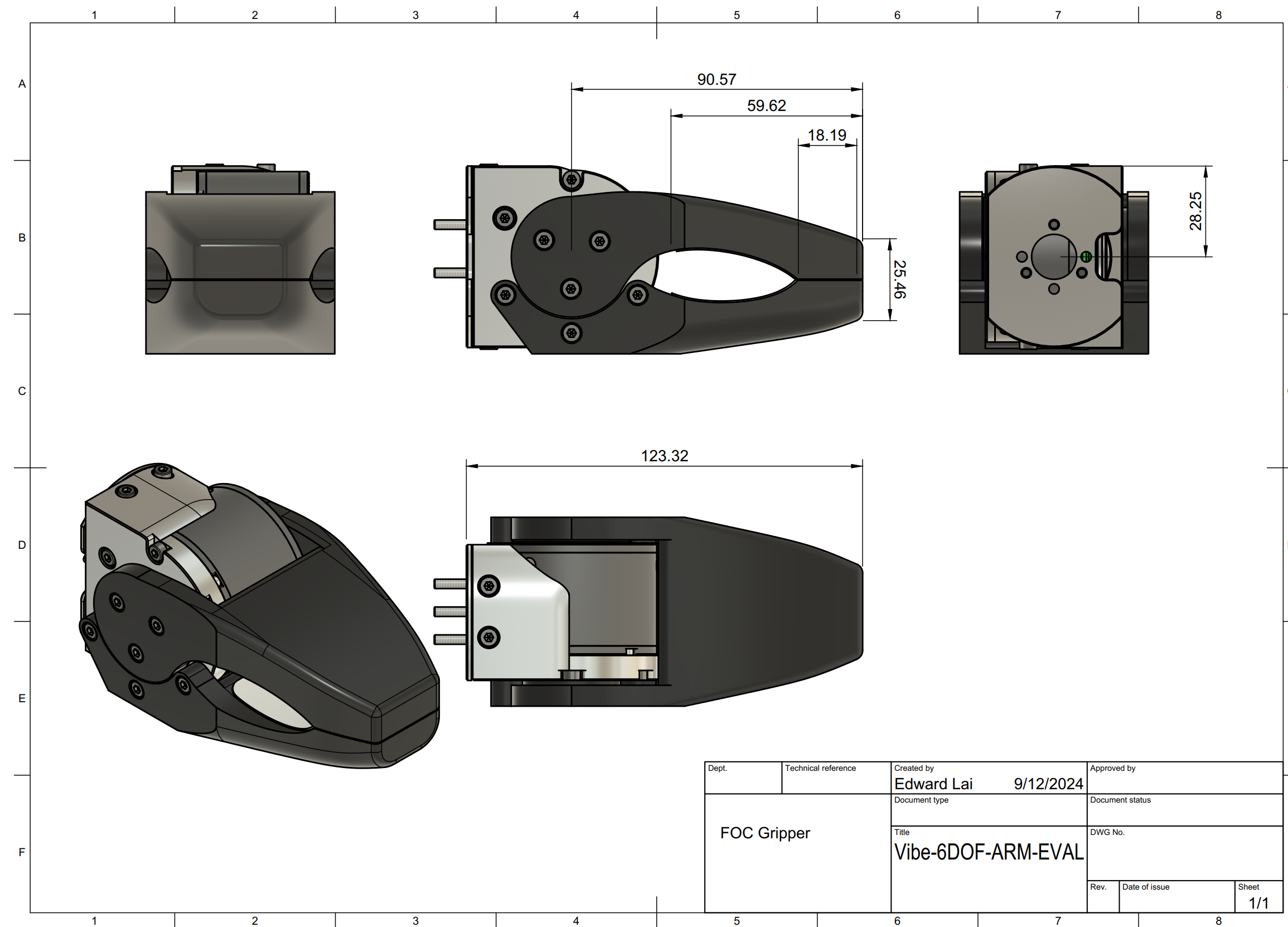
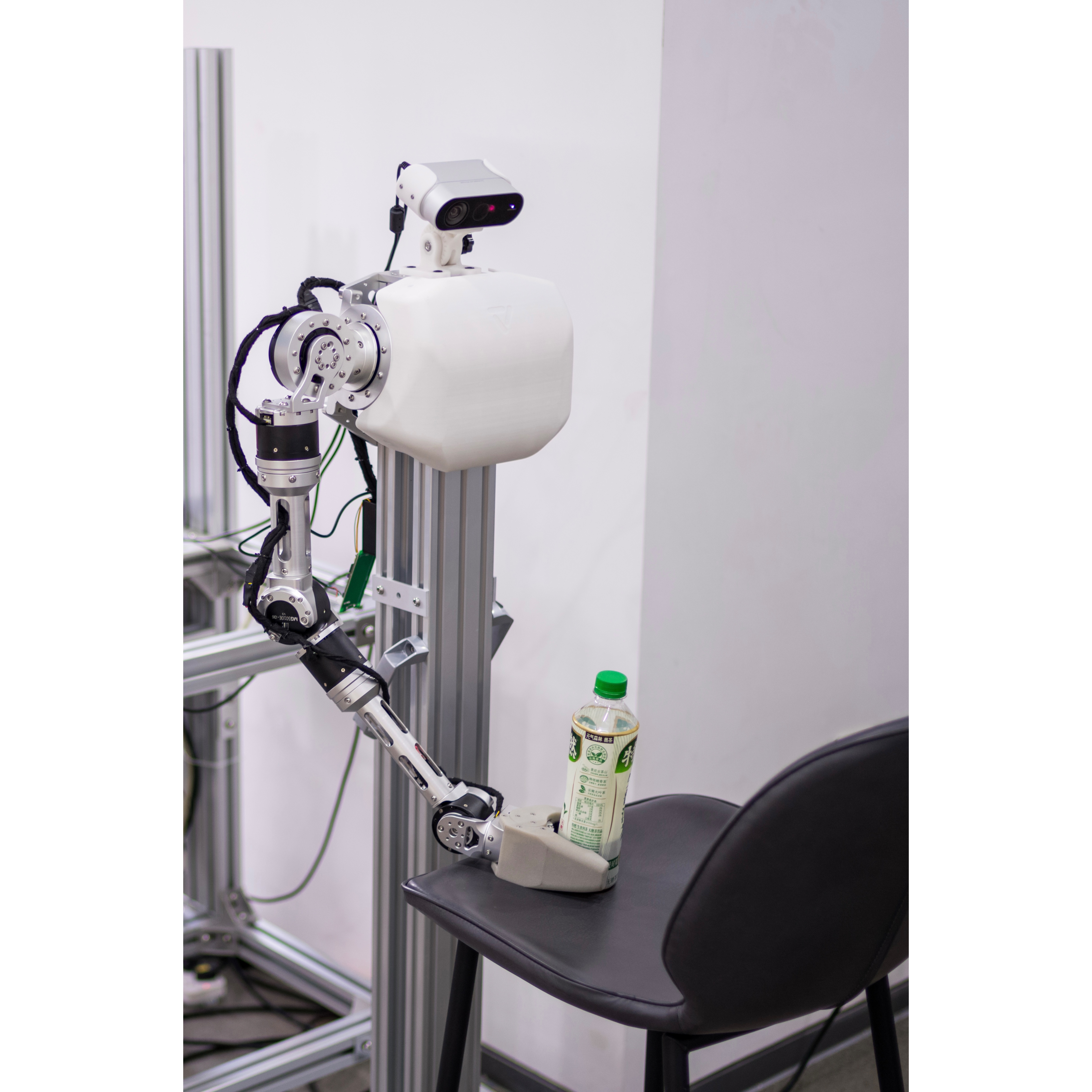
Gripper Design
Inspired by Boston Dynamics’ Spot Arm, this gripper design features a compact actuator that provides significant clamping and gripping force. The fingers have a flat tip for handling thin, flat objects, while the curved palm is designed to grip round objects, such as water bottles.
The gripper actuator is capable of torque control, allowing for precise and adaptable gripping performance.
Single Arm
This section is relatively straightforward compared to optimizing kinematics and dynamics. Begin by importing the motor design and arranging them roughly. Ensure the center plane/shaft of the motor is properly aligned with the kinematic design.
Consider the following:
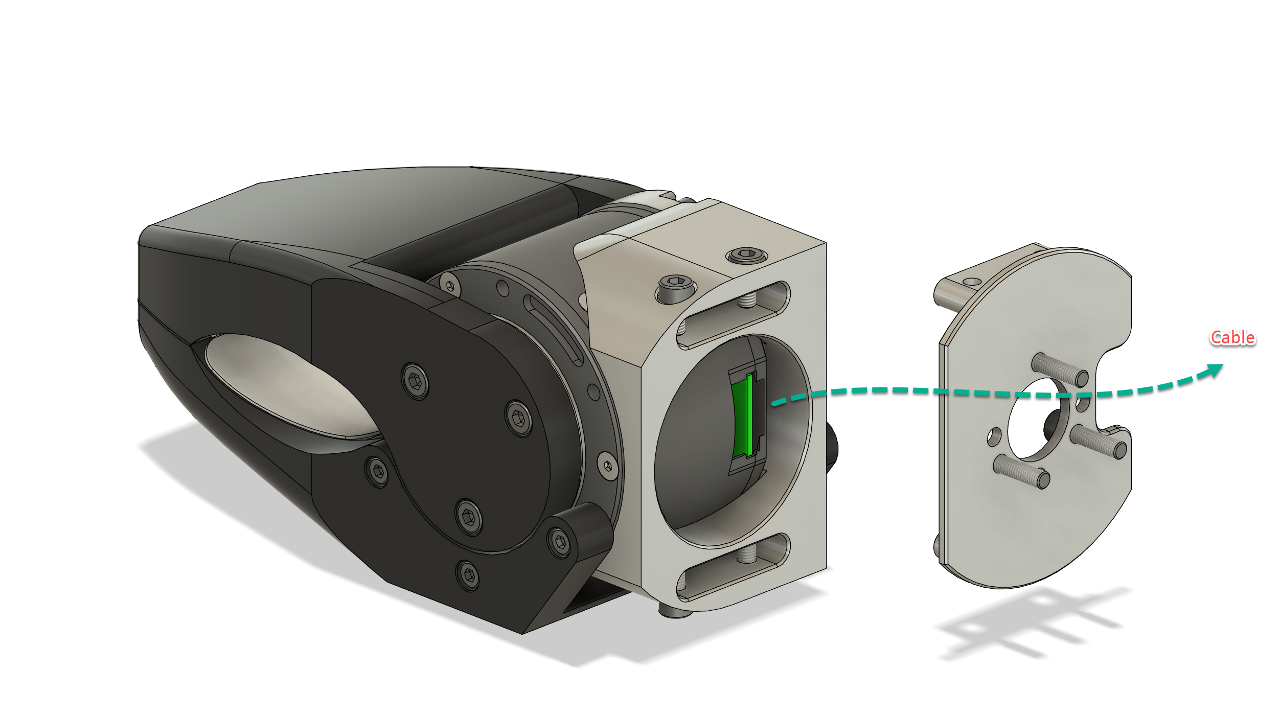
- Cable management and routing
- Reducing link weight as much as possible, with the FEA approach mentioned above.
- Sub-modular design for ease of installation and modular repair
- Maintaining design accuracy in tolerances to minimize mechanical design errors
- Creating good designs with good CNC manufacturability
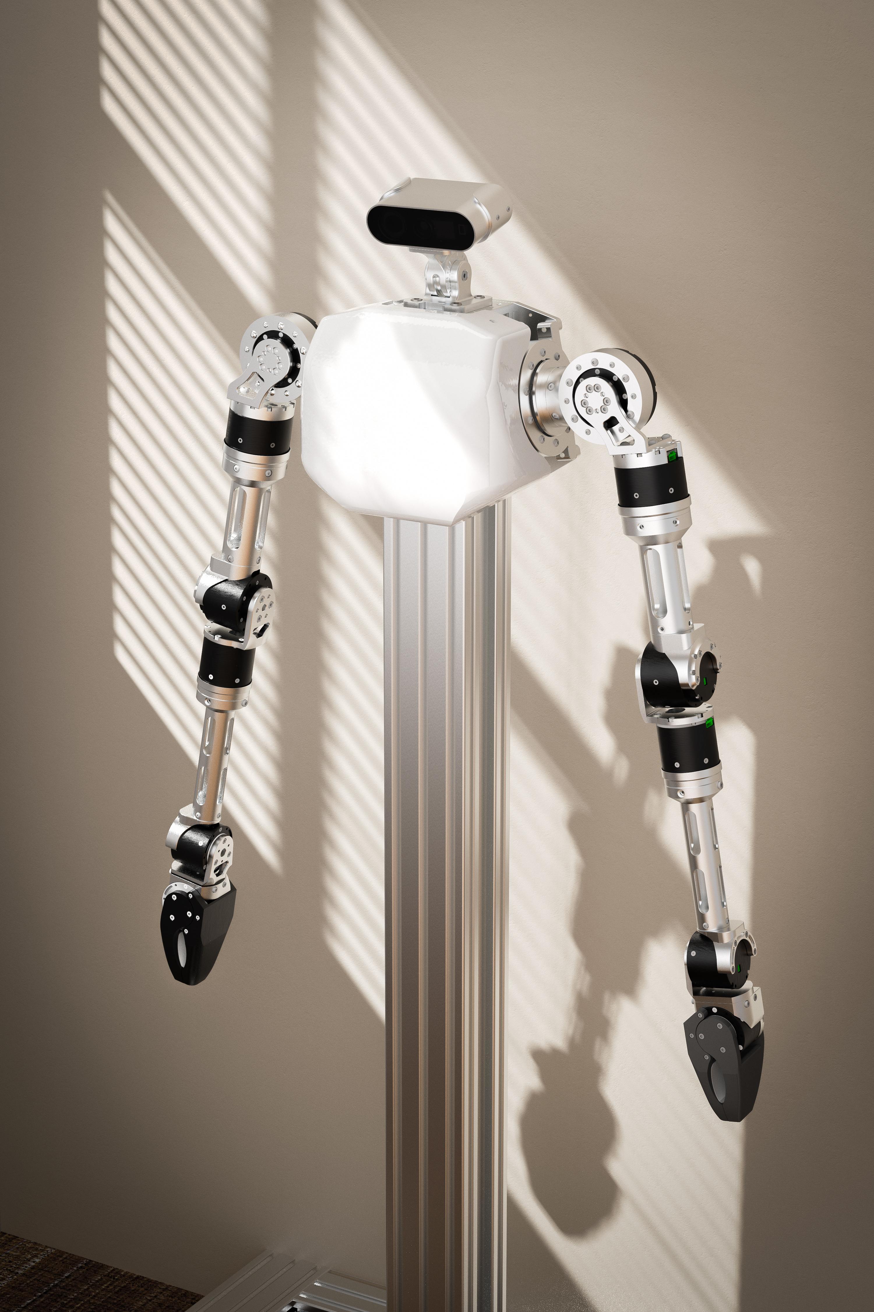
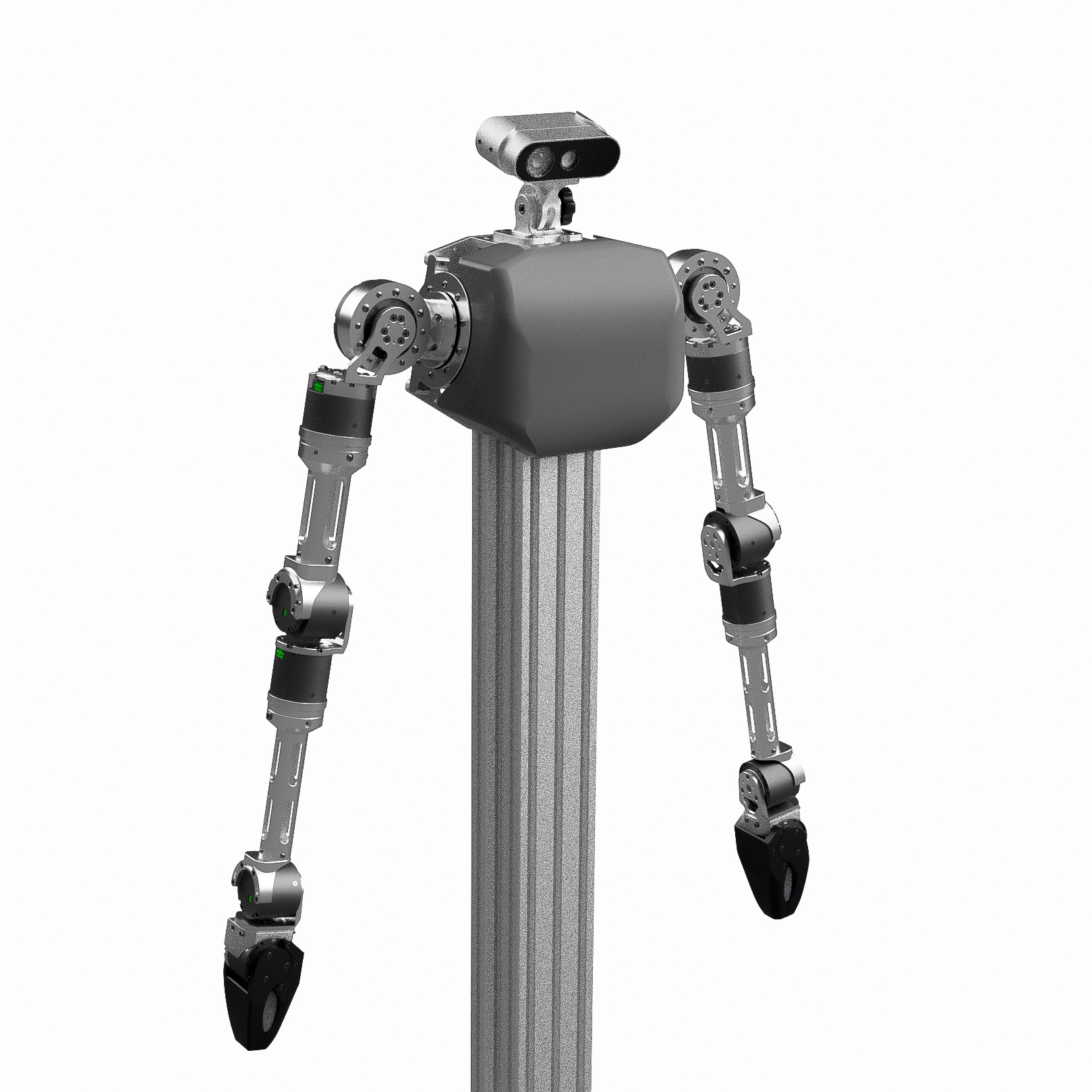
Designed Arm

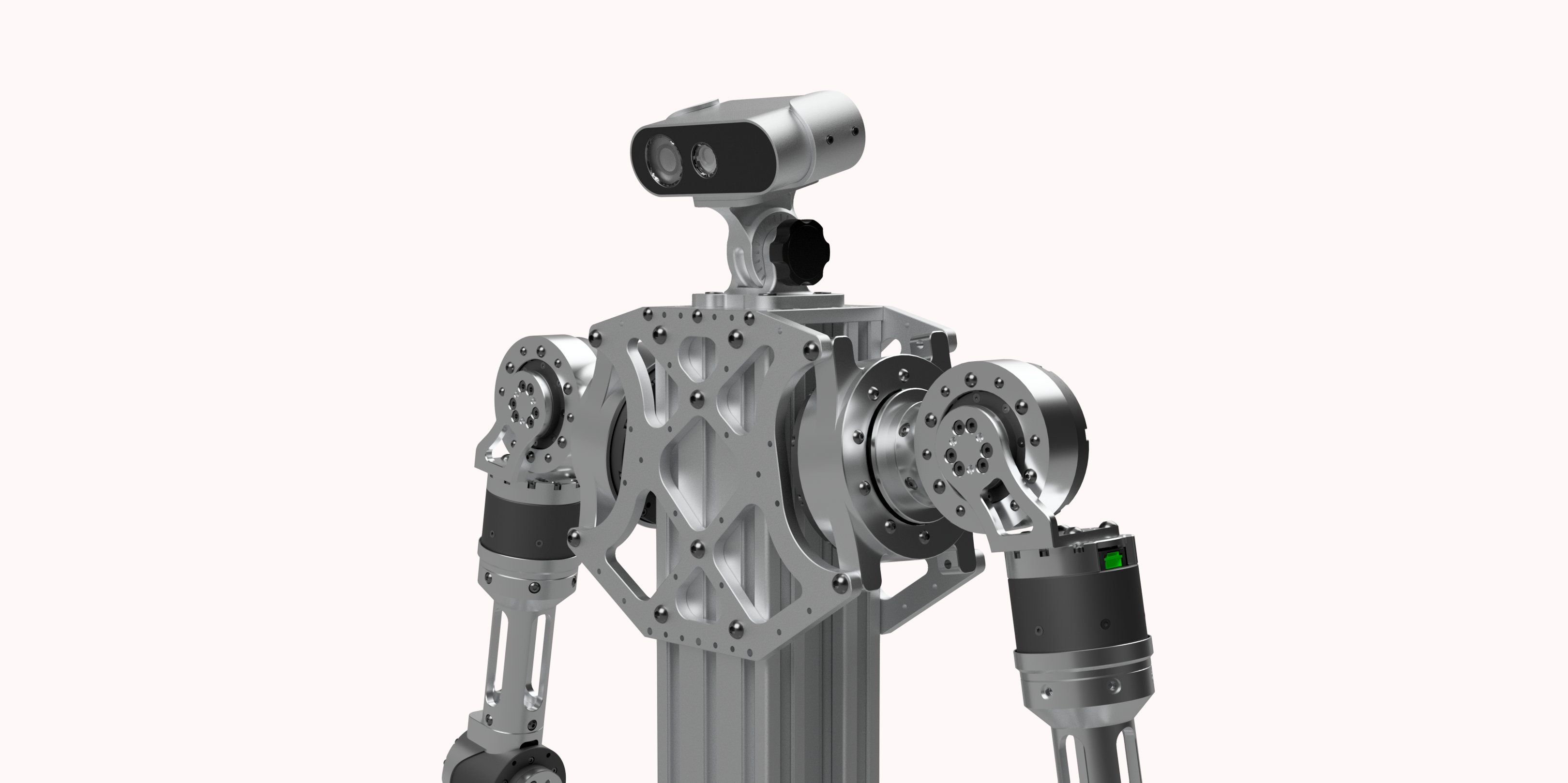
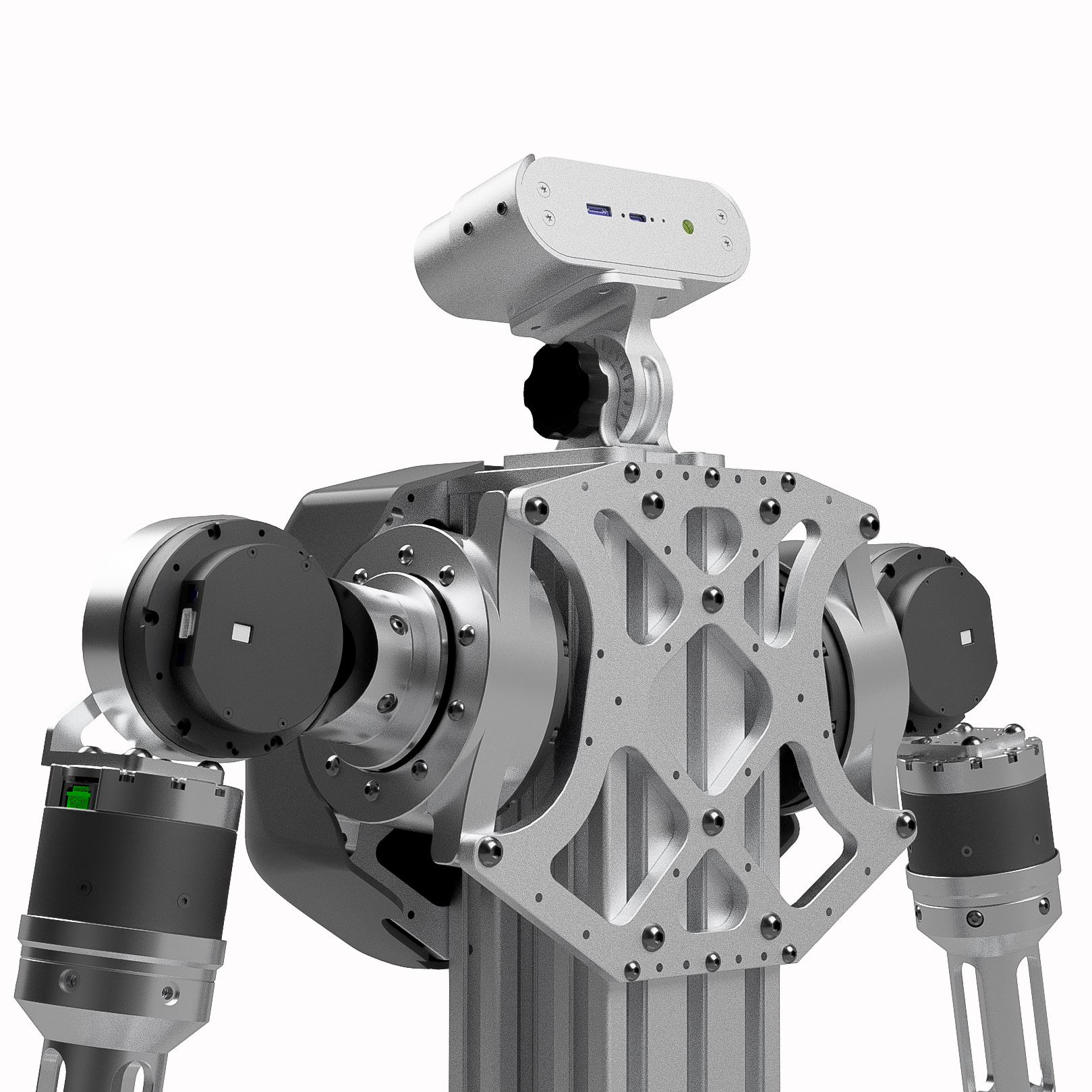
Dual Arm with Body
Kinematics Design
Introduction to Kinematics Design
Kinematics design is a critical aspect of robotics, focusing on the motion of the robot without considering the forces that cause the motion. It involves the study of the robot’s geometry, motion capabilities, and the relationship between its joints and end effectors. By understanding and optimizing the kinematics of the robot, we can ensure smooth and efficient movements, enabling the robot to perform complex tasks with precision.
In this section, we will explore the kinematics design process, including workspace analysis, the use of indices like the Yoshikawa Index, and the steps involved in optimizing the robot’s kinematics for better performance and manipulability.
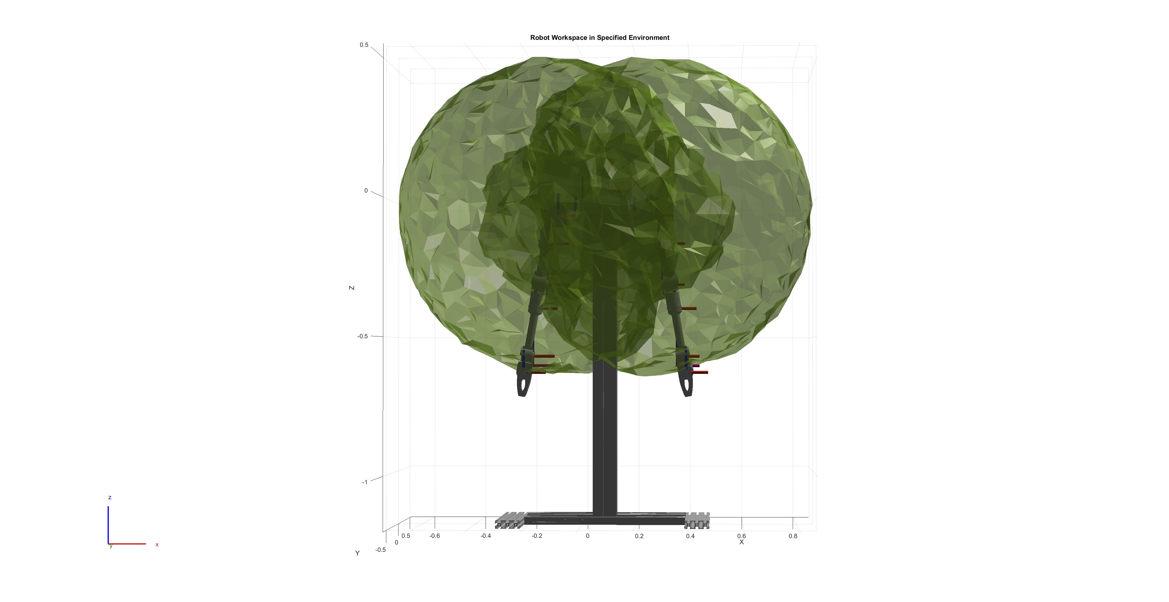
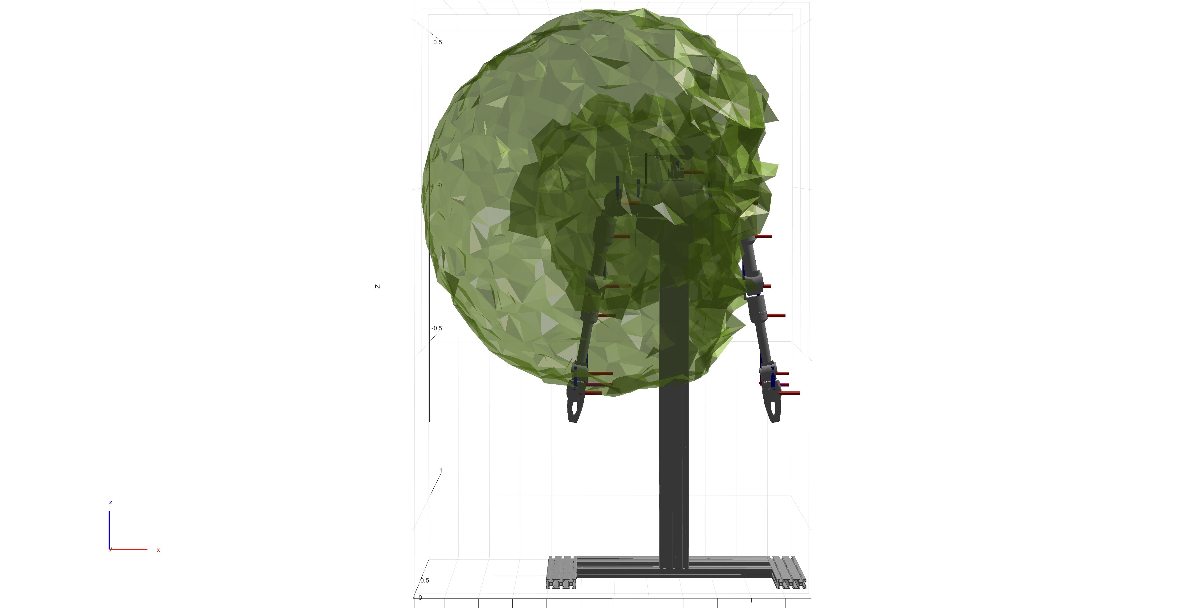
Robotic Arm Workspace Analysis
Yoshikawa Index
The Yoshikawa Index is a measure of a manipulator’s ability to change the position and orientation of its end effector. Higher values indicate greater flexibility and ease of movement, which is crucial for optimal path planning. This index helps identify configurations with high flexibility, ensuring smooth movements and reducing the likelihood of encountering singularities.
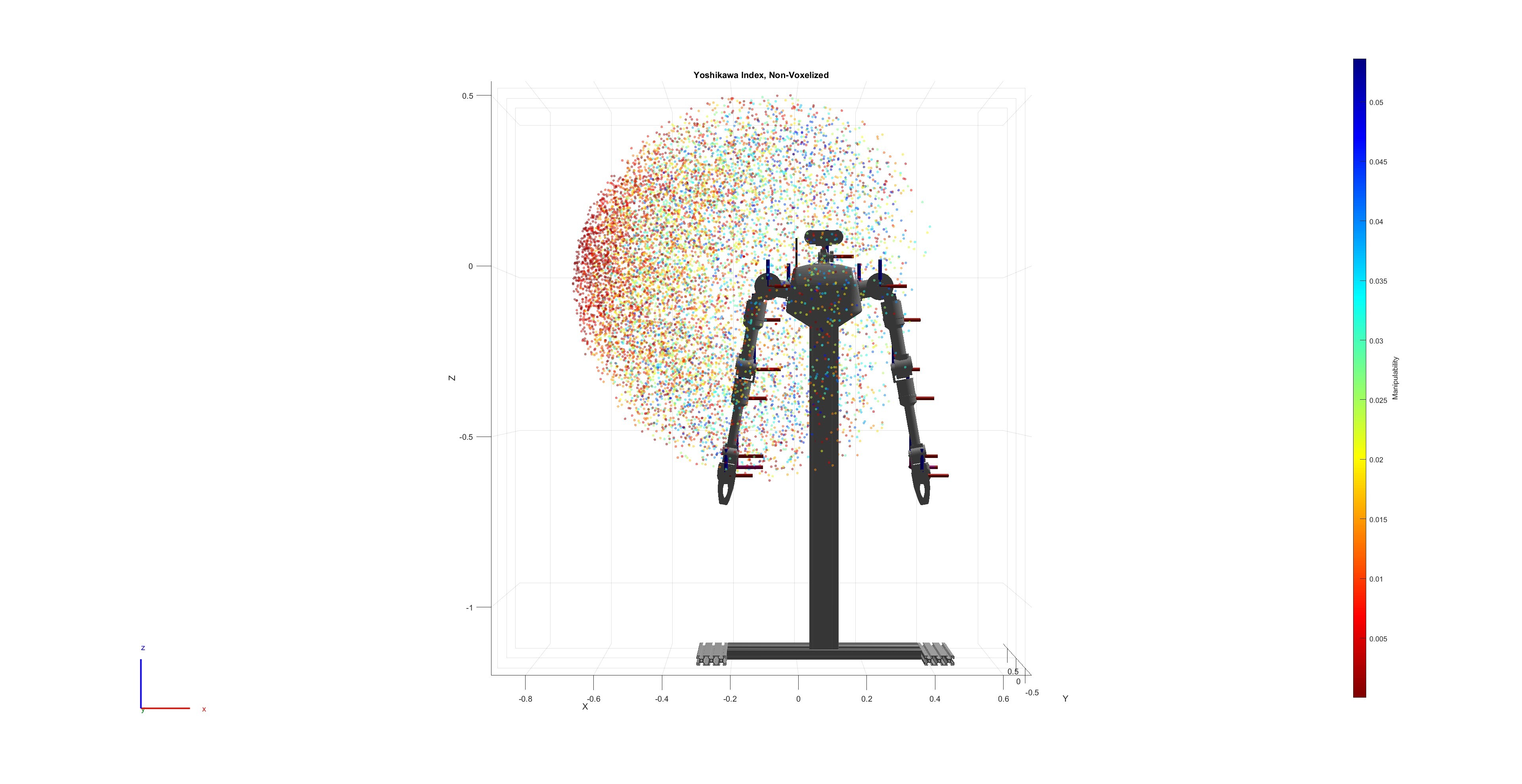
Workspace Analysis and Visualization
Analyzing the workspace of the robotic arm involves visualizing the areas that the arm can reach and the flexibility of its movements. This analysis helps in understanding the limitations and potential improvements in the design.
Findings and Potential Hardware Improvements
- The overall reach in front of the chest is somewhat limited by the elbow.
- The end effector’s 3DOF, where J4 is farther from J5/J6, results in the end effector’s rotational posture “Yoshikawa Index” being more constrained in specific positions.
- The most flexible movement overall is in front of the chest, beyond the elbow joint, which is the most flexible position.
Motion Study and Optimization Process
Designing the robot kinematics involves several steps to ensure optimal performance and manipulability:
- Define Requirements: Establish the range of motion, load capacity, and material constraints for each joint.
- CAD Modeling: Create detailed models of each joint link using CAD software, focusing on minimizing weight while maintaining structural integrity.
- FEA Optimization: Use Finite Element Analysis (FEA) to optimize the weight and mechanical strength of each part by simulating various load conditions and stress distributions.
- Workspace Analysis: Perform workspace analysis to visualize the reach and flexibility of the robotic arm. Use indices like the Yoshikawa Index to identify configurations with high flexibility.
- Iterate and Improve: Based on the findings from the workspace analysis, make necessary hardware improvements to enhance the robot’s manipulability.
By following this process, the design of the robot kinematics is optimized for better performance, ensuring that the robot can perform tasks efficiently and effectively.
The Build
Parts
- 7-DoFs high-performance actuators /Per-Arm (14 DoFs Total.)
- CNC Aluminum Designed Parts
- Some 3D printed parts
- USB to CAN Bus Interface
- Power Bus and connectors.
- ORBBEC Femto Bolt ToF Camera
Build Process
 |
 |
 |
 |
 |
 |
Power Connectors and Power Box
- XT30-2+2 Connector for Serializing Motor’s Power and CAN Bus

- Power/Electronic Box
Finished Build
Software
ROS2 Project
This section details the integration of the robot with the Robot Operating System (ROS2). It includes steps to simplify the CAD model, convert it to URDF, configure motion planning, and integrate the real robot hardware with simulation environments like Gazebo and MoveIt!.
This guide provides an overview of the necessary steps for integrating a new robot. Each item is extensive and will not be covered in detail here.
Simplify the Robot CAD Model and Perform URDF Conversion
- Simplify the CAD model of the robot.
- Convert the simplified model to a URDF (Unified Robot Description Format).
URDF Robot Model
- Import the URDF model.
- Properly define joints, limits, and controller types.
- DEMO: Interact with URDF and check if all joints are defined correctly
- Create a parameter manager for parsing Xacro parameters.
- Configure the IKFast kinematics solver for inverse kinematics.
- Define and configure the controller types.
- Implement collision detection and define constraints.
Setup Planner
- Configure the motion planner.
By completing the steps above, the robot will be ready for simulation, capable of collision checking, motion planning, and inverse kinematics solving. It will be able to perform actions in a virtual environment.
- DEMO: Planner working in Rviz
Incorporate Real Robot
At this point, we have a robot in a virtual environment capable of motion trajectory planning, collision avoidance, and kinematics solving. Now, it is time to implement custom hardware interfaces and controllers. Interacting with real hardware is an exciting step!
-
The top left section of the following graph is completed. Now, we need to implement the bottom half
ros2_controllerand the top right cornerros2_controlfor hardware I/O interaction.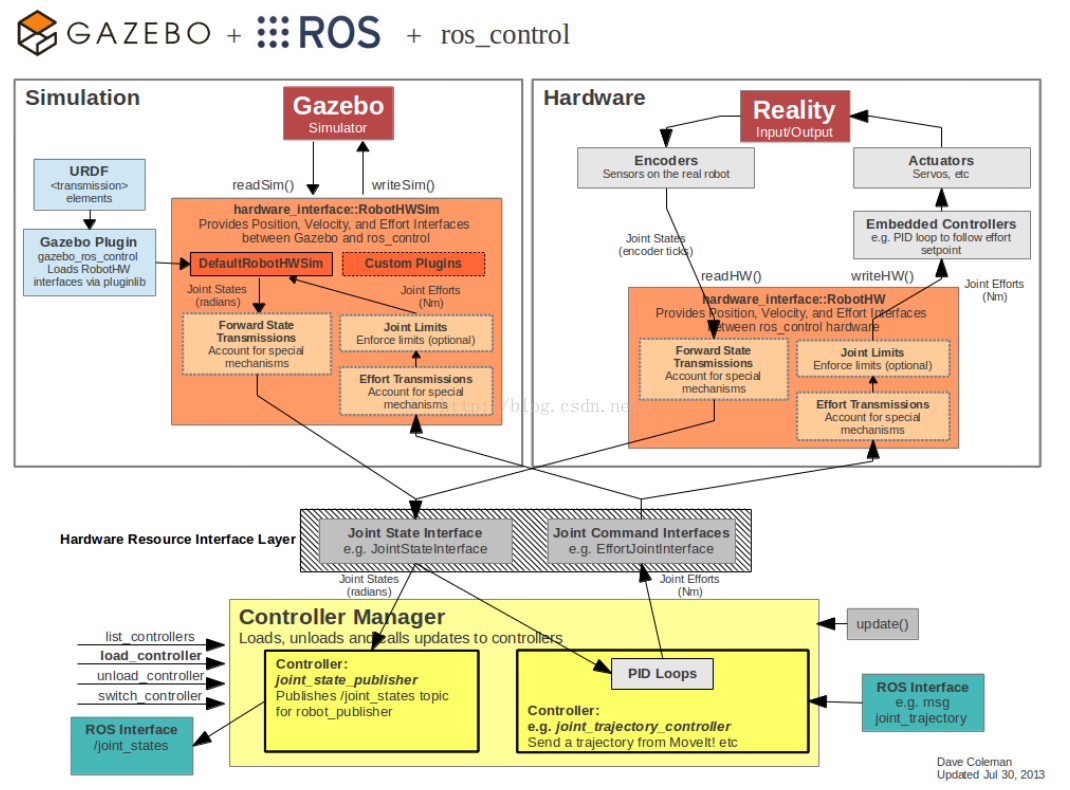
Additional Resources
Introduction to ros2_control and ros2_controllers
ros2_control is a framework for (real-time) control of robots using ROS 2. It provides the necessary infrastructure to integrate hardware interfaces with ROS 2, enabling seamless communication between the robot’s hardware and the ROS 2 ecosystem. The framework is designed to be flexible and extensible, allowing developers to create custom hardware interfaces and controllers tailored to their specific robot hardware.
Key Components of ros2_control
- Hardware Interface: This component acts as a bridge between the robot’s hardware and the ROS 2 control system. It handles the communication with the hardware, reading sensor data, and sending control commands to actuators.
- Controller Manager: The controller manager is responsible for loading, unloading, and managing the lifecycle of controllers. It ensures that the appropriate controllers are running and can switch between different control modes as needed.
- Controllers: Controllers are responsible for implementing specific control strategies, such as position control, velocity control, or effort control. The
ros2_controllerspackage provides a set of standard controllers that can be used out-of-the-box or extended to meet custom requirements.
Using ros2_controllers
The ros2_controllers package provides a variety of controllers that can be used to control different aspects of the robot. Some of the commonly used controllers include:
- Joint State Controller: Publishes the state of the robot’s joints.
- Joint Trajectory Controller: Executes joint trajectory commands.
- Effort Controllers: Control the effort (torque/force) applied to the joints.
- Velocity Controllers: Control the velocity of the joints.
- Position Controllers: Control the position of the joints.
Implementing Custom Hardware Interfaces
To implement a custom hardware interface, you need to create a class that inherits from the hardware_interface::SystemInterface and overrides the necessary methods to handle hardware communication. This includes methods for initializing the hardware, reading sensor data, and writing control commands.
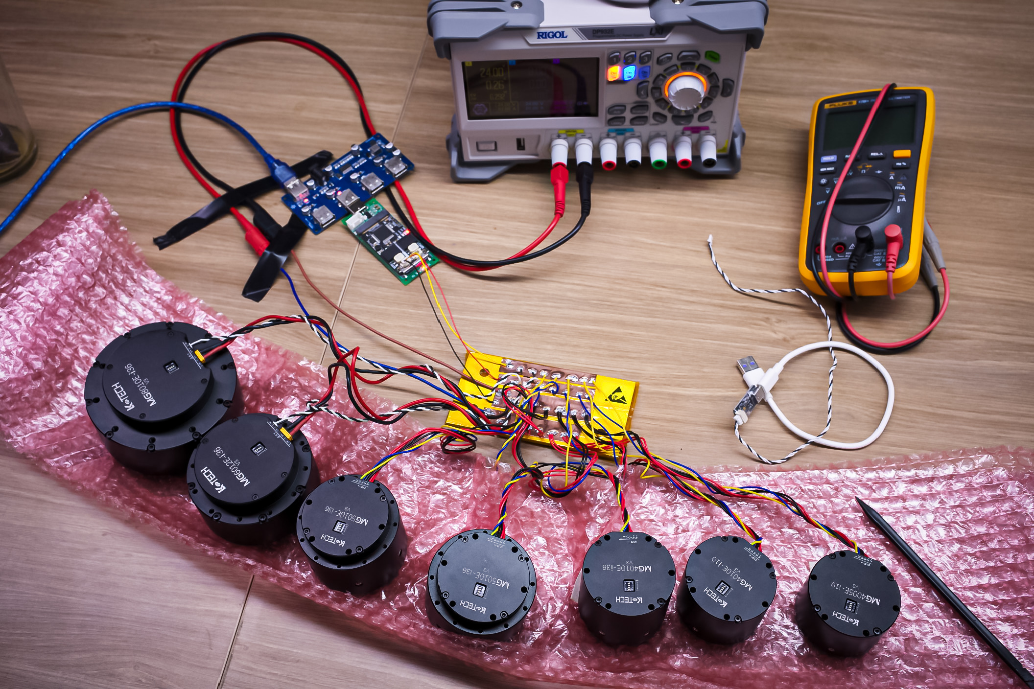
Implement CAN Driver Code
- Develop CAN driver code for the actuators.
- Test motors individually without links to ensure the driver is implemented safely. These motors are really powerful, and trust me, it gets really scary if safety is not implemented.
When Implementing the Driver:
- Select motor IDs and configure motors to corresponding addresses.
- Improve and optimize each motor’s FOC PID parameters to prevent oscillations.
- Implement the CAN bus IO driver to ensure multi-motor control frequency and benchmark CAN bus data throughput.
Integration with Simulation
- Post and listen to joint states and joint commands shared with “Gazebo” or “MoveIt!”.
- This integration links the simulation environment with the real robot, allowing the hardware interface to command motors with joint angles while leveraging planning algorithms and solvers implemented in MoveIt!.
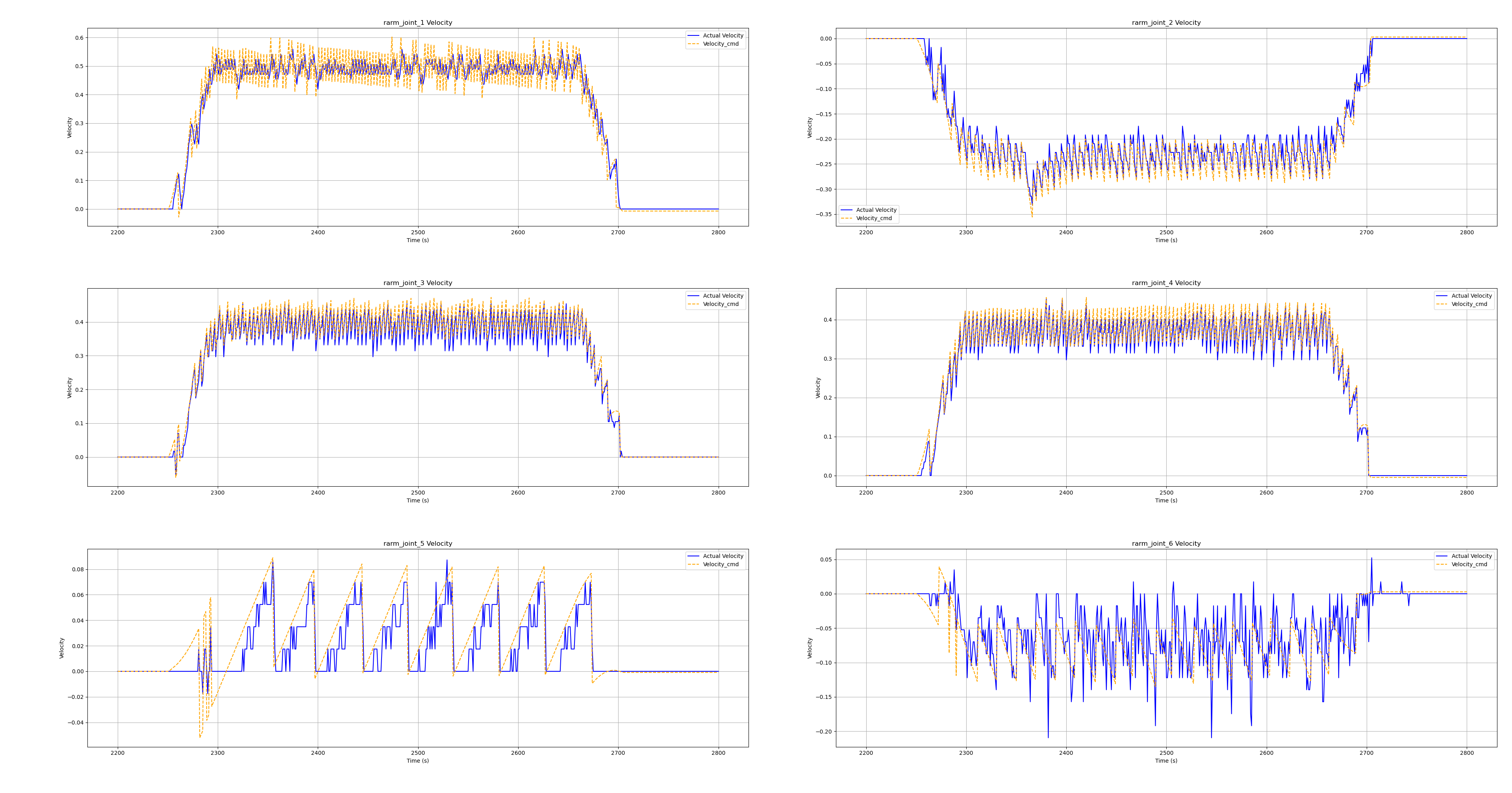
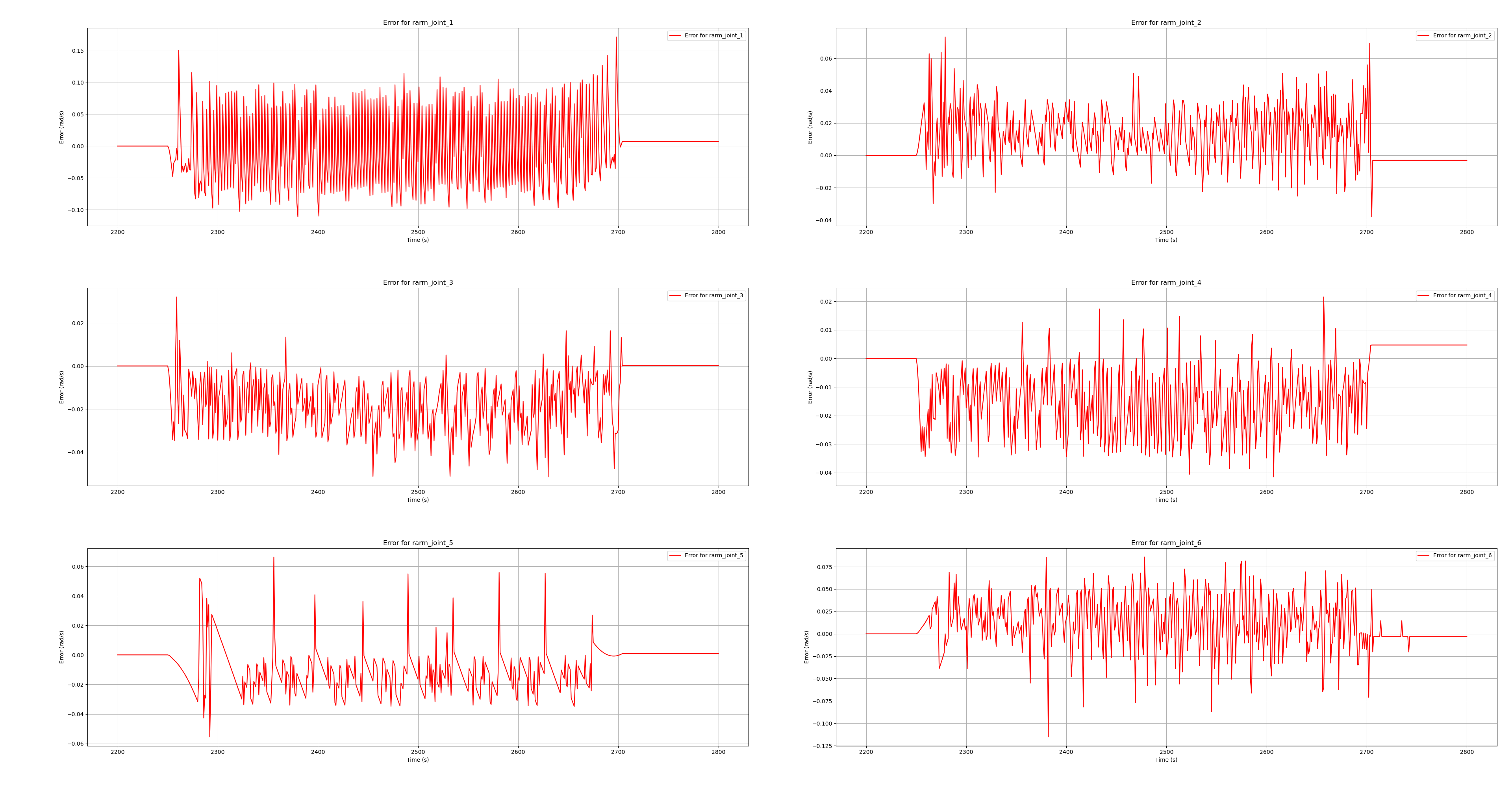
Reducing Jitter and Smoothing Motion: The Importance of Controllers and PIDs
Achieving smooth and precise motion in robotics requires fine-tuning the controllers and PID (Proportional-Integral-Derivative) parameters. Each motor’s PID controller must be carefully adjusted to account for variations in motor characteristics and load conditions. Through extensive testing, I have found that combining velocity and position control with PID significantly reduces jitter and positional errors compared to using position control alone.
Log ploting of actuator position errors:
Updated on: 2024/10/12 “Work In Progress…”
Document Information
- Author: Hsuan Han Lai (Edward Lai)
- Link: https://adwuard.github.io/wip_projects/dual-arm-robot/
- Copyright: Free to share - Non-commercial - No derivatives - Attribution required (Creative Commons 3.0 License)