
Introduction
Firmware development for embedded systems like the Raspberry Pi Pico often involves a repetitive cycle of code, compile, and flash. For the PicoCalc project, this process became particularly tedious, requiring manual button presses to enter bootloader mode before each update. To streamline this workflow, I developed a custom bootloader that eliminates these manual steps by enabling firmware updates directly from an SD card.
This bootloader solves three key challenges:
- Automating firmware updates without requiring physical button presses
- Safely programming flash memory while the code itself runs from flash
- Providing a user interface for selecting and loading different firmware versions
The implementation reads firmware images from an SD card, safely programs them to the appropriate flash memory region, and then transfers execution control to the newly loaded application. This article explores the technical details of how this bootloader works, from memory management to flash programming techniques.
Project Overview
The custom bootloader is part of the Picocalc_SD_Boot repository, which implements a complete solution for SD card-based firmware updates on the RP2040 microcontroller. The project is organized with a modular architecture:
main.c: Core bootloader logic including SD card detection, flash programming, and application launchingconfig.h: Configuration parameters defining critical values likeSD_BOOT_FLASH_OFFSETandMAX_APP_SIZEmemmap_sdcard_app.ld: Custom linker script that defines the memory layout, separating this secondary bootloader and application regionstext_directory_ui.c: Implementation of the text-based UI for navigating and selecting firmware fileskey_event.c: Keyboard event handling for UI navigationi2ckbd/i2ckbd.c: I2C keyboard driver for input detectionlcdspi/lcdspi.c: SPI LCD driver for displaying the firmware selection interface
Understanding how this bootloader works
Raspberry Pi Pico Memory Map
The following table outlines the memory mapping of the Raspberry Pi Pico:
| Memory Region | Start Address | End Address | Size | Description |
|---|---|---|---|---|
| Boot ROM | 0x00000000 | 0x00000FFF | 4 KB | Bootloader ROM |
| XIP (Flash) | 0x10000000 | 0x1FFFFFFF | 16 MB | External Flash Memory (Execute-in-Place) |
| SRAM (Bank 0) | 0x20000000 | 0x2003FFFF | 256 KB | On-chip Static RAM (Bank 0) |
| SRAM (Bank 1) | 0x20040000 | 0x20047FFF | 32 KB | On-chip Static RAM (Bank 1) |
| Peripheral Region | 0x40000000 | 0x5FFFFFFF | 512 MB | Memory-mapped I/O peripherals |
| USB Controller | 0x50100000 | 0x501FFFFF | 1 MB | USB hardware controller |
| SIO (Single-Cycle I/O) | 0xD0000000 | 0xD000FFFF | 64 KB | Single-Cycle I/O block |
| Debug (Cortex-M0+) | 0xE0000000 | 0xE00FFFFF | 1 MB | Debugging and system control space |
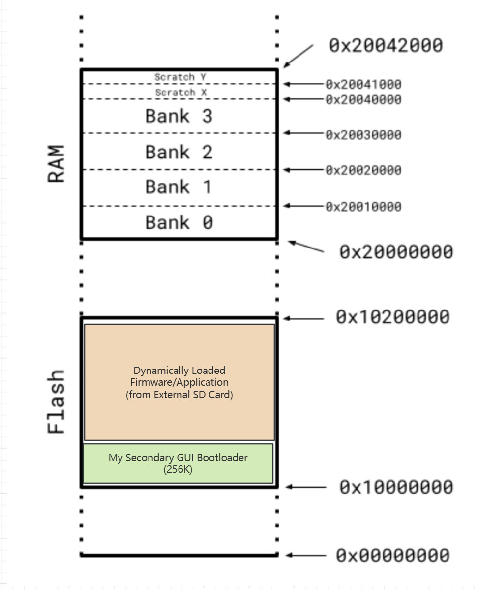
Secondary Bootloader Concept: Enhancing Firmware Loading with SD Card Support
The Raspberry Pi Pico’s built-in bootloader, located in the Boot ROM region, provides essential features such as USB Mass Storage Device (MSD) mode for firmware loading. However, for the PicoCalc project, we aim to extend this functionality by implementing a secondary bootloader. This custom bootloader will enable firmware loading directly from an SD card, offering greater flexibility and convenience.
Key Objectives of the Secondary Bootloader
- SD Card-Based Firmware Loading: The secondary bootloader will allow users to load firmware images stored on an SD card, bypassing the need for USB-based updates.
- Memory Offset Management: The firmware loaded from the SD card will be placed at a specific offset in the flash memory, ensuring it does not overwrite the bootloader itself.
- Application Execution: Once the firmware is loaded into the designated memory region, the bootloader will invoke an assembly call to transfer control to the new firmware’s entry point.
This approach not only complements the existing bootloader functionality but also provides a robust solution for scenarios where USB-based updates are less efficient in some cases.
This will be the new flash layout of custom secondary GUI boortloader and dynamically loaded firmware.
Bootloader Implementation Details
SD Card Detection and Filesystem Initialization
The bootloader begins by checking if an SD card is present using a dedicated GPIO pin:
bool sd_card_inserted(void) {
    // Read the SD card detect pin (active low)
    return !gpio_get(SD_CARD_DETECT_PIN);
}
When an SD card is detected, the bootloader initializes the filesystem using FatFS:
bool fs_init(void) {
    // Initialize SD card
    if (sd_init_driver() != SD_BLOCK_DEVICE_ERROR_NONE) {
        return false;
    }

    // Mount filesystem
    FRESULT fr = f_mount(&fs, "", 1);
    return fr == FR_OK;
}
Flash Programming and Safety
One of the most critical aspects of the bootloader is safely programming flash memory. Since the RP2040 executes code from flash, we must ensure that the code responsible for erasing and programming flash runs from RAM. This is achieved using the __not_in_flash_func attribute:
__not_in_flash_func(bool) load_program(const char* filename) {
    FIL file;
    FRESULT fr;
    UINT bytes_read;
    uint8_t buffer[FLASH_PAGE_SIZE];

    // Open firmware file
    fr = f_open(&file, filename, FA_READ);
    if (fr != FR_OK) return false;

    // Get file size
    FSIZE_t file_size = f_size(&file);
    if (file_size > MAX_APP_SIZE) {
        f_close(&file);
        return false;
    }

    // Erase flash sectors
    uint32_t sectors_to_erase = (file_size + FLASH_SECTOR_SIZE - 1) / FLASH_SECTOR_SIZE;
    uint32_t flash_offset = SD_BOOT_FLASH_OFFSET;

    for (uint32_t sector = 0; sector < sectors_to_erase; sector++) {
        uint32_t interrupt_state = save_and_disable_interrupts();
        flash_range_erase(flash_offset + sector * FLASH_SECTOR_SIZE, FLASH_SECTOR_SIZE);
        restore_interrupts(interrupt_state);
    }

    // Program flash with firmware data
    flash_offset = SD_BOOT_FLASH_OFFSET;
    f_lseek(&file, 0);

    while (true) {
        fr = f_read(&file, buffer, FLASH_PAGE_SIZE, &bytes_read);
        if (fr != FR_OK || bytes_read == 0) break;

        uint32_t interrupt_state = save_and_disable_interrupts();
        flash_range_program(flash_offset, buffer, bytes_read);
        restore_interrupts(interrupt_state);

        flash_offset += bytes_read;
    }

    f_close(&file);
    return true;
}
The key safety measures in this implementation include:
- Disabling interrupts during flash operations with
save_and_disable_interrupts() - Using the
__not_in_flash_funcattribute to ensure the function runs from RAM - Checking firmware size against
MAX_APP_SIZEto prevent overflow - Processing the firmware in chunks that match the flash page size
Application Validation and Launching
Before jumping to the newly loaded application, the bootloader validates the firmware by checking its vector table:
bool is_valid_application(uint32_t app_address) {
    // Check if the stack pointer in the vector table points to a valid RAM address
    uint32_t* vector_table = (uint32_t*)app_address;
    uint32_t stack_pointer = vector_table[0];

    // Stack pointer should be within RAM bounds
    return (stack_pointer >= SRAM_START && stack_pointer <= SRAM_END);
}

__not_in_flash_func(void) launch_application_from(uint32_t app_address) {
    // Get the application's vector table
    uint32_t* vector_table = (uint32_t*)app_address;

    // Get the stack pointer and reset handler from the vector table
    uint32_t stack_pointer = vector_table[0];
    uint32_t reset_handler = vector_table[1];

    // Disable interrupts
    __asm volatile ("cpsid i");

    // Reset peripherals if needed
    // ...

    // Set the vector table offset register
    SCB->VTOR = app_address;

    // Set the stack pointer and jump to the reset handler
    __asm volatile(
        "msr msp, %0\n"
        "bx %1\n"
        : : "r" (stack_pointer), "r" (reset_handler) : "memory"
    );
}
This validation ensures we only attempt to boot valid firmware images, preventing crashes from corrupted or incomplete files.
Memory Layout and Linker Script
The memory layout is a critical aspect of the bootloader design. The custom linker script memmap_sdcard_app.ld defines how memory is allocated between the bootloader and application firmware:
MEMORY {
    BOOT_FLASH (rx) : ORIGIN = 0x10000000, LENGTH = 256K
    APP_FLASH (rx)  : ORIGIN = 0x10000000 + 256K, LENGTH = PICO_FLASH_SIZE_BYTES - 256K
    RAM (rwx)       : ORIGIN = 0x20000000, LENGTH = 256K
}
The bootloader occupies the first 256KB of flash memory, while the application firmware is loaded at an offset defined by SD_BOOT_FLASH_OFFSET (256KB). The maximum application size is calculated as:
#define SD_BOOT_FLASH_OFFSET (256 * 1024)  // 256KB
#define MAX_APP_SIZE (PICO_FLASH_SIZE_BYTES - SD_BOOT_FLASH_OFFSET)
This arrangement protects the bootloader from being overwritten while providing ample space for application firmware. For a standard 2MB Pico, this leaves 1.75MB available for the application.
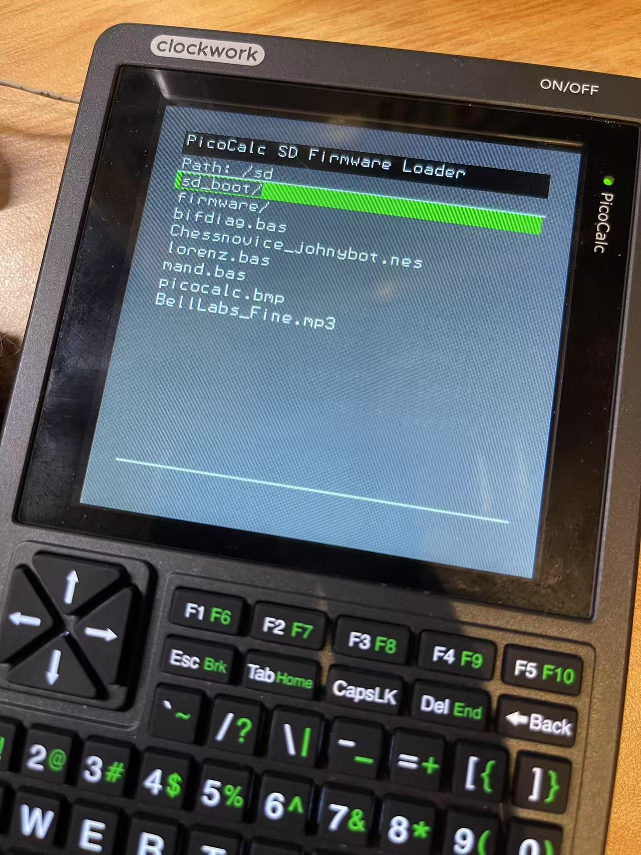
User Interface for Firmware Selection
The bootloader implements a text-based directory navigation system in text_directory_ui.c that allows users to browse and select firmware files from the SD card:
void directory_ui_init(const char* root_dir, firmware_selected_callback_t callback) {
    strncpy(current_dir, root_dir, MAX_PATH_LENGTH);
    firmware_selected_callback = callback;
    current_selection = 0;
    refresh_directory_listing();
    display_directory();
}

void directory_ui_handle_key(key_event_t key) {
    switch (key) {
        case KEY_UP:
            if (current_selection > 0) {
                current_selection--;
                display_directory();
            }
            break;

        case KEY_DOWN:
            if (current_selection < file_count - 1) {
                current_selection++;
                display_directory();
            }
            break;

        case KEY_ENTER:
            if (current_selection < file_count) {
                char full_path[MAX_PATH_LENGTH];
                snprintf(full_path, MAX_PATH_LENGTH, "%s/%s",
                         current_dir, file_list[current_selection].name);

                if (file_list[current_selection].is_directory) {
                    // Navigate into directory
                    strncpy(current_dir, full_path, MAX_PATH_LENGTH);
                    current_selection = 0;
                    refresh_directory_listing();
                    display_directory();
                } else {
                    // Select firmware file
                    firmware_selected_callback(full_path);
                }
            }
            break;

        default:
            break;
    }
}
This UI system:
- Displays a list of files and directories from the SD card
- Allows navigation using up/down keys
- Supports entering subdirectories and selecting firmware files
- Triggers a callback when a firmware file is selected
The UI integrates with the I2C keyboard driver (i2ckbd.c) for input and the SPI LCD driver (lcdspi.c) for display output, creating a complete user experience for firmware selection.
Demonstration
Upon powering up, the bootloader initializes and presents a user-friendly directory interface. This GUI allows users to navigate the SD card and select a firmware file. Once a firmware file is chosen, the bootloader seamlessly loads it into memory and transfers control to the newly selected firmware.
Integration of External References
This bootloader implementation draws inspiration from several key resources:
-
Pete Warden’s article on executing code from RAM when programming flash on the RP2040 highlights the critical need for the
__not_in_flash_funcattribute. This technique is essential because attempting to erase or program a flash sector while executing code from that same sector would cause the processor to crash. -
Kevin Boone’s exploration of memory layout and linker scripts for the RP2040 provided valuable insights into how to structure the memory map to protect the bootloader while allowing application firmware to be loaded at a specific offset.
These references informed several design decisions in the bootloader:
- The separation of bootloader and application regions in flash memory
- The technique for safely programming flash while running from flash
- The approach to validating and launching application firmware
Conclusion
The custom bootloader for the PicoCalc significantly improves the development workflow by eliminating the need for manual button presses during firmware updates. By implementing SD card-based firmware loading, it provides several technical benefits:
The complete source code for this bootloader is available in the Picocalc_SD_Bootrepository, where you can explore the implementation details further and adapt the approach for your own projects.
Contributing and Source Code
Document Information
- Author: Hsuan Han Lai (Edward Lai)
- Link: https://adwuard.github.io/writting-custom-bootloader-for-RPI-Pico/
- Copyright: Free to share - Non-commercial - No derivatives - Attribution required (Creative Commons 3.0 License)